CA10B前刹车调整臂外壳的机械加工工艺及铣12端面夹具设计【铣小端面夹具工艺装备优秀课程毕业设计含4张CAD图纸带过程工序卡片】-jjsj33
CA10B前刹车调整臂外壳的机械加工工艺规程及铣12端面夹具设计【铣小端面夹具】
摘要
调整臂外壳的加工工艺及专用夹具设计,考虑到零件在机床运行过程中所受冲击不大,零件结构又比较简单,故选择铸造。调整臂外壳的主要加工面是调整臂的几个端面、方槽和孔,由于面的加工精度要比孔的加工精度容易保证。因此,采用先面后孔的原则,以保证加工精度。该设计中,应先以大端外圆加工出两端面,再以该基准面加工小端面和相应的孔。在其余工序中,均以此孔与端面为定位基准,加工调整臂的孔、槽和一些端面,在整个加工过程中,用到了车床、铣床和钻床。
关键词: 调整臂外壳,加工工艺,夹具设计
ABSTRACT
Adjusting the processing technology of the arm shell and the design of the special fixture, taking into account the parts in the operation of the machine in the process of little impact, the parts structure is relatively simple, so choose casting. The main processing surface of the adjusting arm shell is a few end faces, square grooves and holes of the adjusting arm, and the machining accuracy of the shell is easy to guarantee compared with the processing precision of the hole. Therefore, the principle of "first face, rear hole" is adopted to ensure the machining accuracy. In this design, should be the first to end outer circle processing two end, then the datum processing and the corresponding small end hole. In the rest of the process, the hole and end face are used as the positioning datum to adjust the hole, groove and end face of the adjusting arm. The lathe, milling machine and drilling machine are used in the whole process.
Key words: adjusting arm shell, processing technology, fixture design
目录
摘要 I
ABSTRACT II
第一章 绪论 1
第二章 零件的分析 2
3.1零件的作用 2
3.2零件的工艺分析 2
第三章 工艺规程设计 2
4.1确定毛坯的制造形式 3
4.2基准的选择 3
4.3制定工艺路线 3
第四章 夹具设计 25
4.1 问题的提出 25
4.2 定位基准的选择 25
4.3切削力和夹紧力的计算 25
4.4 定位误差分析 26
4.5定向键与对刀装置设计 26
4.6 夹具设计及操作简要说明 27
参考文献 30
致谢 31
【详情如下】【需要咨询购买全套设计请加QQ1459919609】
CA10B前刹车调整臂外壳的机械加工工艺规程及铣12端面夹具设计【铣小端面夹具】.doc
前刹车调整臂外壳.dwg
前刹车调整臂外壳毛坯.dwg
参考卡片及说明书
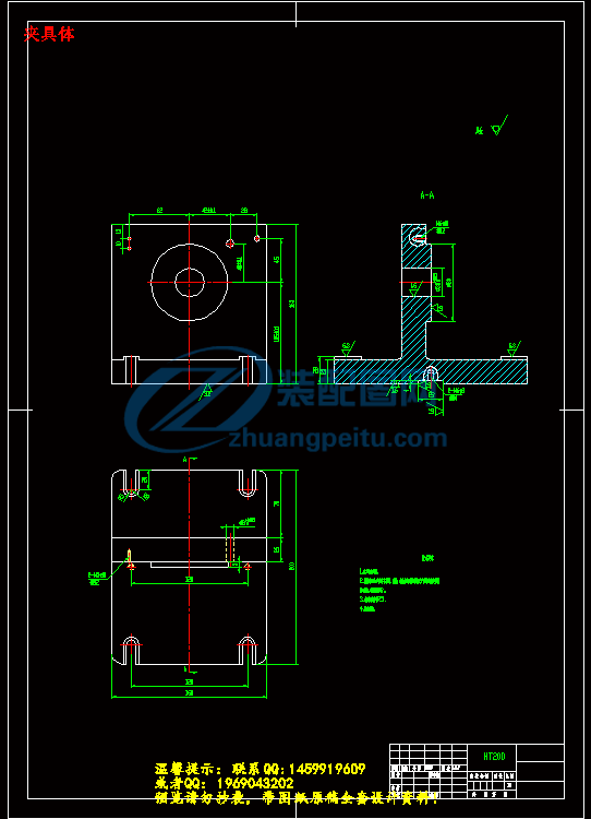
夹具体.dwg
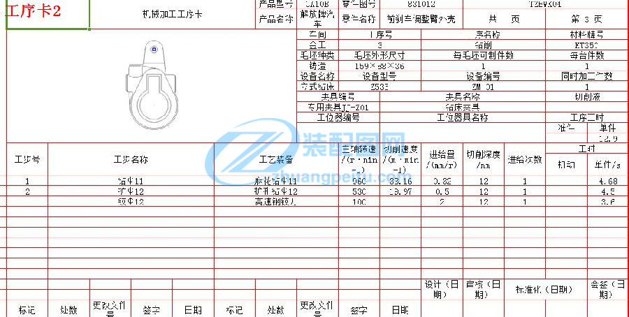
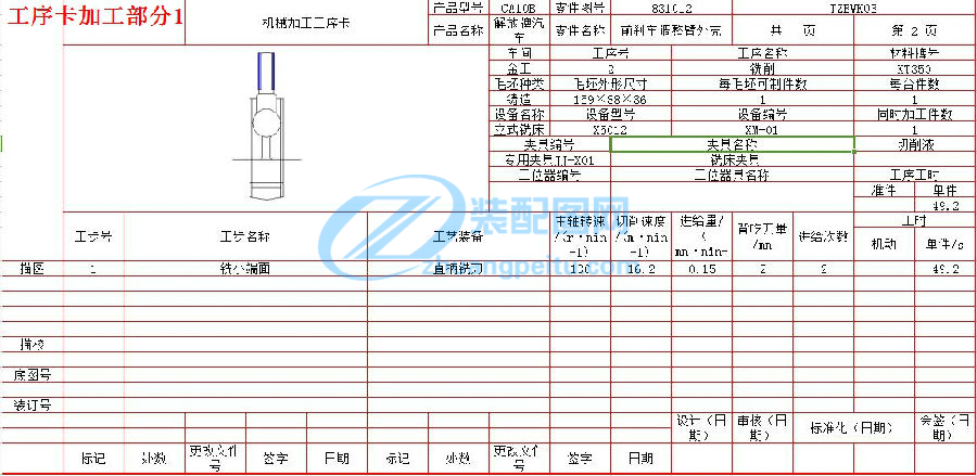
工序卡片.xlsx
工艺过程卡卡.xlsx
文件清单.txt
铣小端面装配图.dwg
