标致206轿车左/右前轮罩支架落料模具设计【优秀课程毕业设计+含7张CAD图纸+带51页加正文2.1万字】-cymj01
【详情如下】【需要咨询购买全套设计请加QQ1459919609】
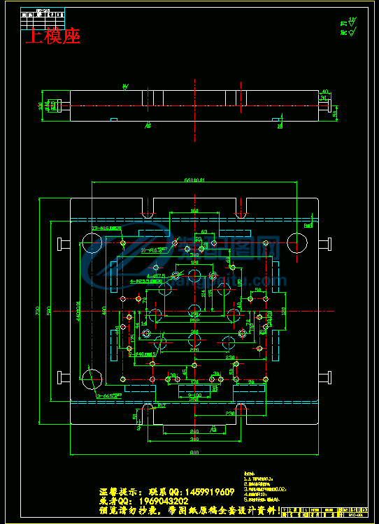
上模座.dwg
下模座.dwg
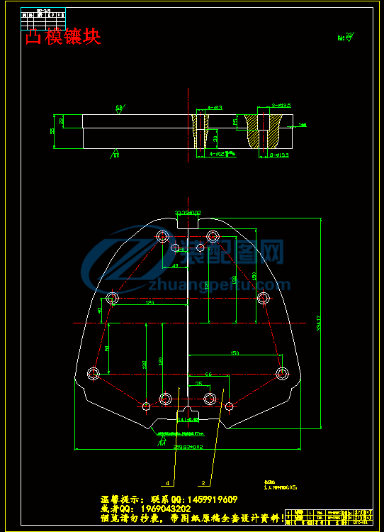
凸模镶块.dwg
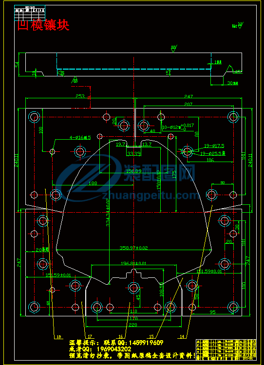
凹模镶块.dwg
图纸总汇.dwg
文件清单.txt
落料装配图.dwg
说明书正文.doc
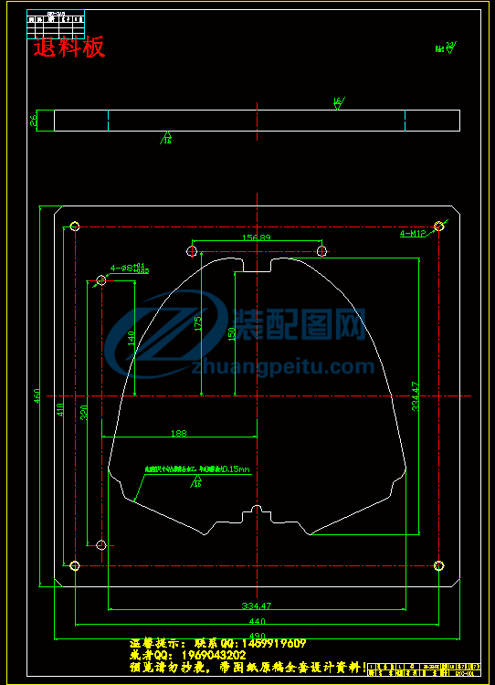
退料板.dwg
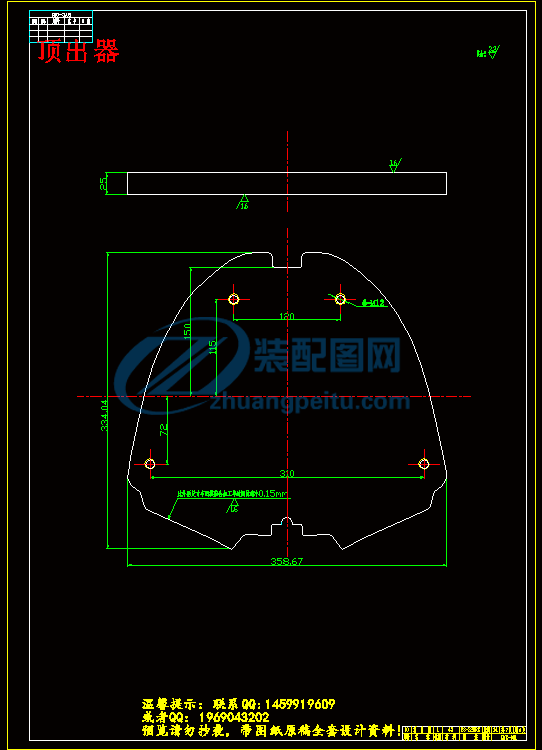
顶出器.dwg
摘 要
本篇论文论述了模具工业在国内的发展与现状,并介绍了AutoCAD和Pro/e在模具设计中的结合应用,详细论述左/右前轮罩支架落料模具设计过程。据零件的形状和工艺性要求,进行工艺分析,制定了零件的冲压成形工艺方案,重点阐述了落料模具设计。论述左/右前轮罩支架落料模具方案的比较和选择。根据零件形状、结合实际制定出合理的排样设计。详细介绍了左/右前轮罩支架落料模具的结构设计及关键零部件设计(包括冲裁力、卸料力和顶出力的计算,弹簧、卸料螺钉的选择,凸、凹模设计,上、下模板,导柱、导套的选择等)。简述了冲压设备的选择,并且编制了模具主要零部件制造工艺。简要阐述了利用AutoCAD进行模具设计过程和Pro/e三维建模,以及两者的结合,虚拟装配和干涉检查。
关键词:落料模具设计;工艺分析;结构设计;虚拟装配
Abstract
This thesis discussed the development and actuality of die industry in our country, and introduced the combined use of AutoCAD and Pro/e in die design. Particularly discussed the designing process of pushing mold of the right and left cover bracket of the front wheel. Arts and crafts analyzing based on the arts and crafts requirement and part’s shape. Brought forward the punching and forming schemes of the part. Stressed the design process of excision m- old. Compared and adopted the schemes of pushing mold of the right and left cover bracket of the front wheel. Designed the arrangements of the parts on the material based on the shape of the parts and practice condition. Particularly discussed the designing of the mold’s main parts’ structure, including calculating the punching force, protrusion force, choosing springs and bolts, designing concave and convex die, choosing the fixing boards and guiding pole and sheath. Simply discussed how to choose the pressing equipment. Arranged manufacture arts and crafts for the main parts of mould. Simply discussed the designing process of the die by combined use of AutoCAD and Pro/e. Did virtual assemblage and interference verification.
Keyword: punch die design; arts and crafts analysis; structure design; virtual assemblage
目 录
第一章 概论…………………………………………………………………………………1
1.1模具工业的发展与现状 ………………………………………………………………1
1.1.1 模具工业发展概况………………………………………………………………1
1.1.2模具工业未来前景………………………………………………………………2
1.2 CAD在模具设计中的应用 ……………………………………………………………3
1.3 Pro/e在模具设计中的用 ……………………………………………………………4
第二章 工艺分析与模具结构形式设计……………………………………………………5
2.1 工艺分析………………………………………………………………………………5
2.1.1冲裁件的形状与尺寸要求 ………………………………………………………5
2.1.2左/右前轮罩支架结构分析………………………………………………………5
2.2 制定工艺方案…………………………………………………………………………6
2.2.1零件工艺要求……………………………………………………………………6
2.2.2工序顺序的编排与工序组合……………………………………………………6
第三章 工艺计算……………………………………………………………………………8
3.1 毛坯展开计算 ………………………………………………………………………8
3.2 排样优化设计 ………………………………………………………………………8
3.2.1搭边………………………………………………………………………………8
3.2.2 排样方案设计 …………………………………………………………………9
3.2.3 排样方案比较 …………………………………………………………………9
3.2.4 排样方案选择 …………………………………………………………………10
3.3 冲压力的计算 ………………………………………………………………………11
3.3.1冲裁力的计算 …………………………………………………………………11
3.3.2退料力、顶出力的计算 ………………………………………………………12
3.3.3降低冲裁力的方法 ……………………………………………………………12
3.4计算压力中心 ……………………………………………………………………13
第四章 冲压设备选择………………………………………………………………………14
4.1典型冲压设备概述(曲柄压力机)…………………………………………………14
4.2冲压设备选择原则……………………………………………………………………15
4.2.1冲压设备类型的选择……………………………………………………………15
4.2.2冲压设备规格的确定……………………………………………………………15
4.3选择冲压设备…………………………………………………………………………16
第五章 模具结构设计…………………………………………………………………17
5.1 模具总体结构设计…………………………………………………………………17
5.1.1方案分析…………………………………………………………………………17
5.1.2方案比较与选择…………………………………………………………………17
5.2模具闭合高度分析 …………………………………………………………………18
5.2.1闭合高度概述……………………………………………………………………18
5.2.2估算模具闭合高度………………………………………………………………19
第六章 模具主要零部件设计………………………………………………………………20
6.1 凸、凹模设计…………………………………………………………………………20
6.1.1计算冲裁间隙……………………………………………………………………20
6.1.2凸、凹模刃口尺寸计算…………………………………………………………21
6.1.3凸模结构设计……………………………………………………………………23
6.1.4凹模结构设计……………………………………………………………………24
6.1.5凸、凹模最终确定结构…………………………………………………………25
6.2 退料板设计 …………………………………………………………………………26
6.3 顶出装置设计 ………………………………………………………………………26
6.4 弹簧的选择 …………………………………………………………………………27
6.4.1 弹簧选择原则 …………………………………………………………………27
6.4.2 退料弹簧的选择 ………………………………………………………………28
6.4.3 顶出弹簧的选择 ………………………………………………………………28
6.5螺钉的选择……………………………………………………………………………29
6.5.1 退料螺钉的选择 ………………………………………………………………29
6.5.2 顶出螺钉的选择 ………………………………………………………………30
6.6定位方式设计…………………………………………………………………………30
6.7导向零件选择 ……………………………………………………………………30
6.7.1 分析 ……………………………………………………………………………31
6.7.2 导柱、导套选择…………………………………………………………………31
6.8支撑零件选择(上、下模座)……………………………………………………32
6.8.1上、下模座选择原则……………………………………………………………32
6.8.2上、下模座的选择………………………………………………………………32
第七章 模具总图绘制………………………………………………………………………33
7.1绘制二维工程图………………………………………………………………………33
7.2 三维建模……………………………………………………………………………33
7.3干涉检查、分析………………………………………………………………………34
第八章 模具主要零部件制造工艺的编制…………………………………………………35
8.1上模座…………………………………………………………………………………35
8.2下模座…………………………………………………………………………………36
8.3凸模……………………………………………………………………………………37
8.4退料板…………………………………………………………………………………38
8.5顶出器…………………………………………………………………………………39
8.6导柱……………………………………………………………………………………40
8.7导套……………………………………………………………………………………40
第九章 结论…………………………………………………………………………………41
结束语 ………………………………………………………………………………………42
致谢 …………………………………………………………………………………………43
参考文献 ……………………………………………………………………………………44
