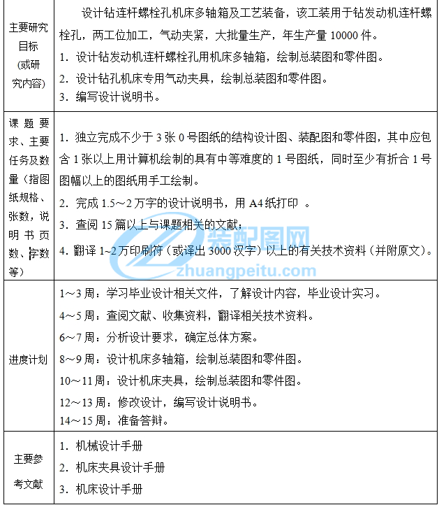
连杆螺栓孔钻孔夹具及多轴箱设计【钻2-Φ16孔气动夹具优秀课程毕业设计+含19张CAD带任务书+45页加正文1.98万字】
【详情如下】【需要咨询购买全套设计请加QQ1459919609】
任务书.doc
圆柱销.dwg
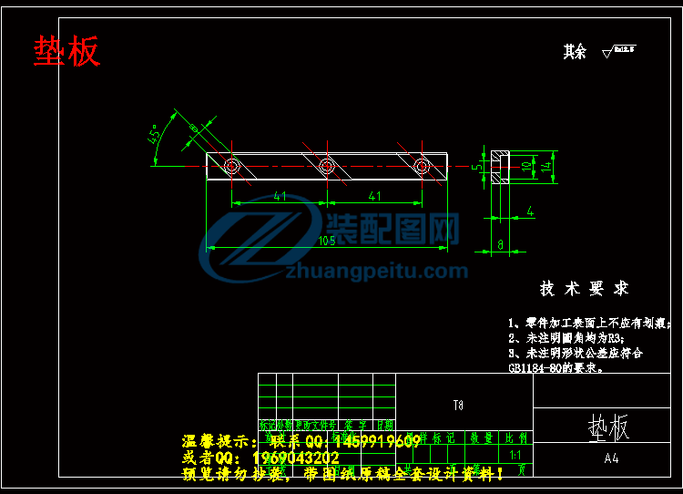
垫板.dwg
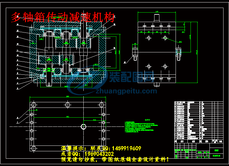
多轴箱传动减速机构.dwg
多轴箱装配图.dwg
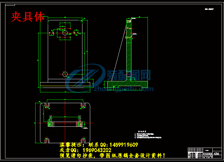
夹具体.dwg
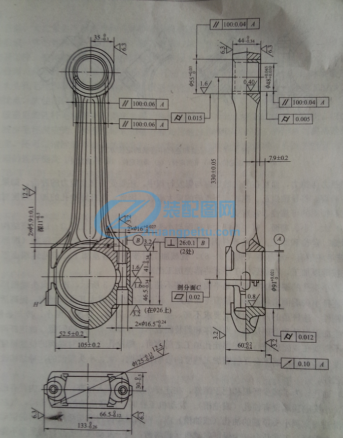
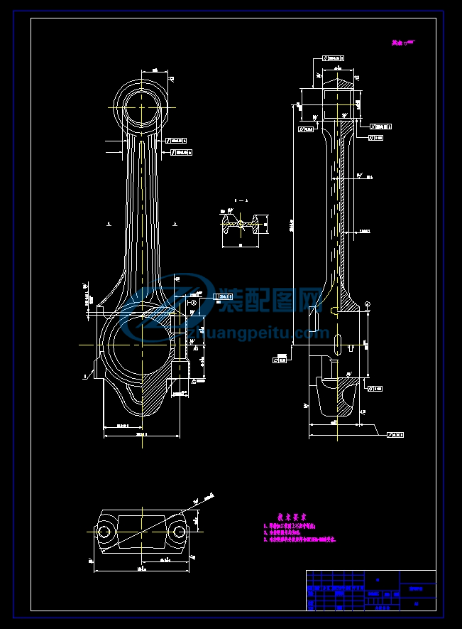
工件零件图.dwg
文件清单.txt
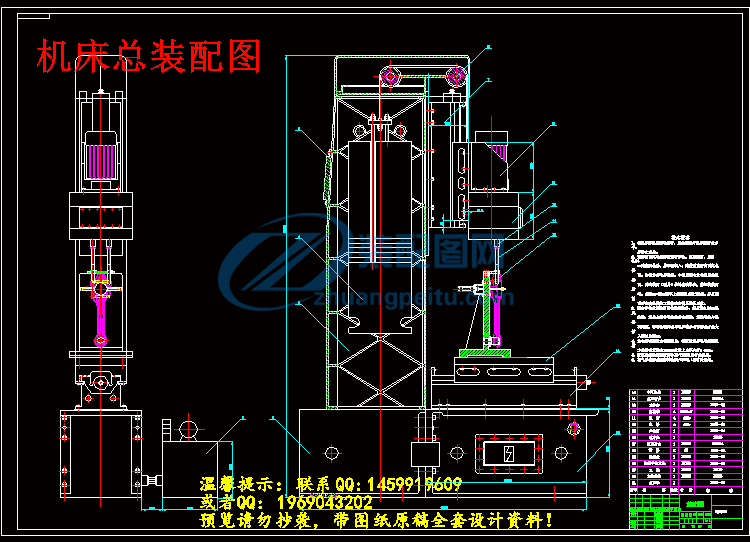
机床总装配图.dwg
正文.doc
轴02-03.dwg
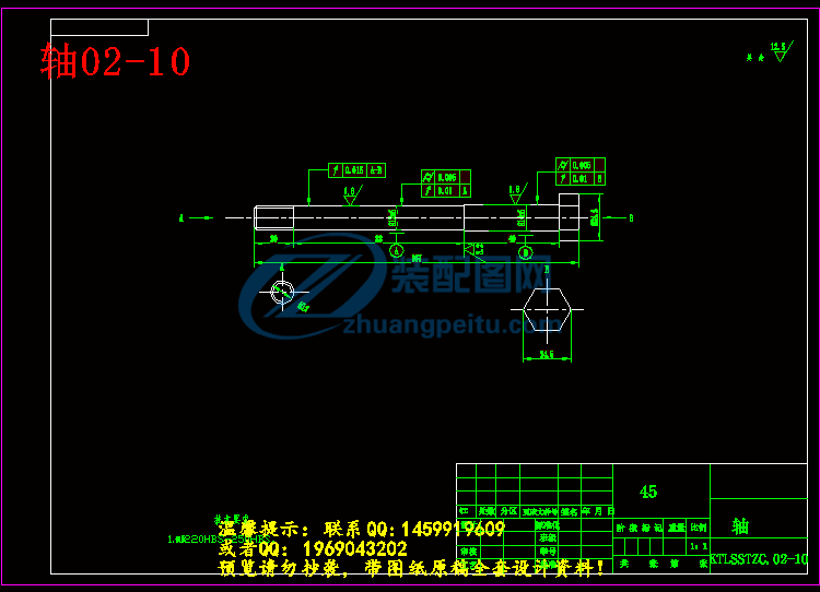
轴02-10.dwg
轴03-07.dwg
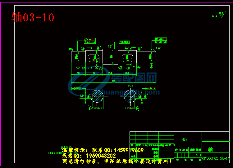
轴03-10.dwg
轴03-11.dwg
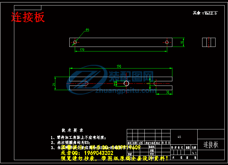
连接板.dwg
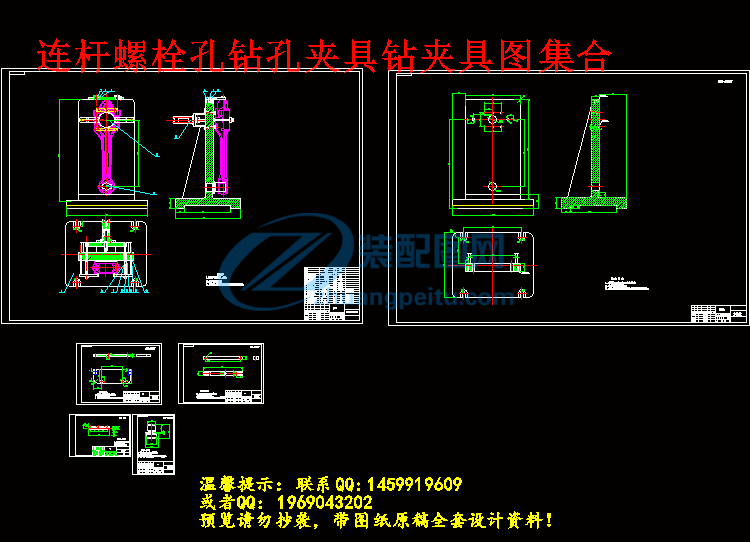
连杆螺栓孔钻孔夹具钻夹具图集合.dwg
钻2-Φ16孔气动夹具.dwg
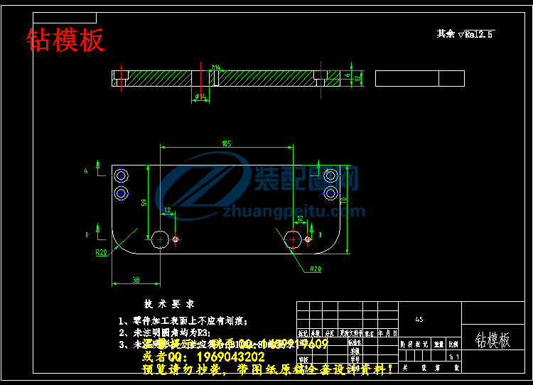
钻模板.dwg
齿轮02-07.dwg
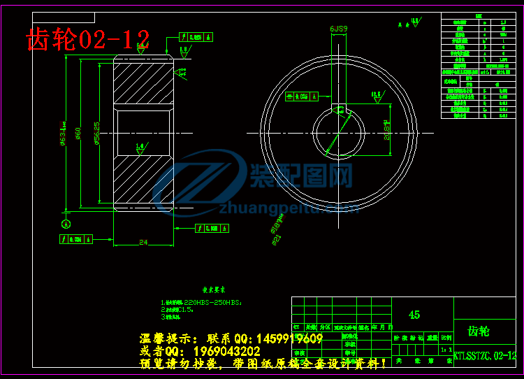
齿轮02-12.dwg
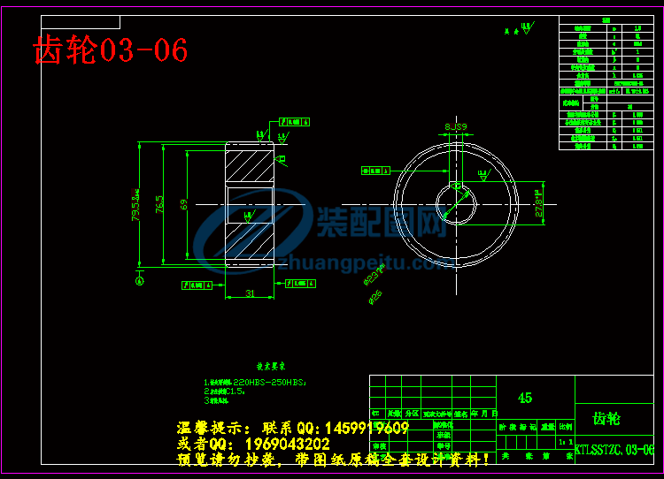
齿轮03-06.dwg
齿轮03-13.dwg
连杆螺栓孔钻孔夹具及多轴箱设计【钻2-Φ16孔气动夹具】
连杆螺栓孔钻孔夹具及多轴箱设计【钻2-Φ16孔气动夹具
摘 要
在机械制造各行业的工艺过程中广泛应用着各种不同的,用以固定加工对象,使之占有正确位置,以便接受施工的一种工艺装备,统称为夹具。因此,无论是在机械加工,装配,检验,还是在焊接,热处理等冷,热工艺中,以及运输工作中都大量采用夹具。但在机械加工中应用最为广泛的是金属切削机床上使用的夹具,我们称其为机床夹具。它在保证产品优质,高产,低成本,充分发挥现有设备的潜力,以便工人掌握复杂或精密零件加工技术,以减轻繁重的体力劳动等诸方面起着巨大的作用。因此,机床夹具的设计和使用是促进生产迅速发展的重要工艺措施之一。为此,在本次毕业设计时,选择了机床夹具设计。
本文主要围绕机床钻孔夹具设计为中心。用以钻连杆零件,首先通过参观实习让我们对夹具设计有了初步的了解,特别是对钻模夹具设计的了解更为深刻。然后,在导师的指导下,对夹具设计方案进行分析和选择。选定方案后,。通过查阅相关夹具设计书籍和相关图例在钻孔夹具设计过程中,。在查阅了相关文献后完成外文翻译。参考相关资料完成夹具的总体设计。
此次设计为连杆钻孔多轴箱的机械设计。设计主要介绍了钻孔多轴箱的设计原理、调整方法及设计计算过程。通过预先给定的加工要求可确定所需的计算参数,进而依据可调立式钻孔多轴箱的设计原理来设计计算并校核各个部位的零件,然后进行组装。本次设计可从五大方面进行设计。通过预先给定的加工要求计算并进行了双头钻头的设计、传动系统减速箱的设计、传动系统电机的选用、可以保证较高的加工精度和孔间相对位置精度。
关键词:气动夹具;电动机;变速箱;
Connecting rod bolt-hole drilling jig and multi-axle pneumatic clamp design
Abstract
In the process machinery manufacturing industries are widely used in a variety of different, to fix the object to be processed so that it occupies a correct position in order to receive a construction of process equipment, collectively referred to as fixtures. Therefore, whether in machining, assembly, inspection, or welding, heat treatment, cold and hot processes, as well as extensive use of transport work in both fixtures. But in machining the most widely used is the fixture for use on metal-cutting machine tools, jigs and fixtures we call it. It is to ensure product quality, high yield, low cost, the full potential of existing equipment in order to grasp the complexity of workers or precision parts processing techniques to reduce the heavy manual labor and other aspects play a huge role. Therefore, the design and use of jigs and fixtures is one of the important technical measures to promote the rapid development of production. For this reason, in this graduation project, select the tool fixture design.
In this paper, the machine drilling fixture design around the center. For drill rod parts, first by visiting fixture design expertise allows us to have a preliminary understanding, especially understanding the jig fixture design is more profound. Then, under the guidance of instructors, for fixture design analysis and selection. After selecting the program. Through access to relevant books and related fixture design legend in drilling fixture design process. Access to the relevant literature in foreign language translation is completed. References relevant information to complete the overall design fixture.
The design of multi-axle drilling rod mechanical design. Design introduces the drilling of multi-axle box design principles, methods and design adjustment calculation. By processing requirements given in advance to determine the parameters required for the calculation, and then based on adjustable vertical drilling multi-axle box design principles to design calculations and check all parts of the parts, then assembled. This design can be designed from five aspects. By pre-processing requirements of a given calculation and design of the double-headed drill, drive train gearbox design, selection of the motor drive system, ensuring both high precision and accuracy of the relative position of the hole.
Keywords: pneumatic clamps; motor; gearbox;
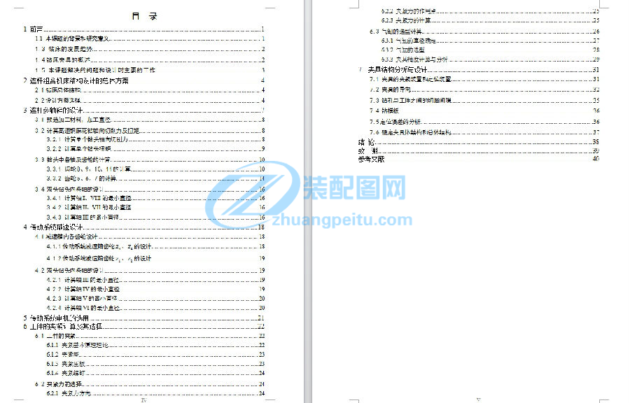
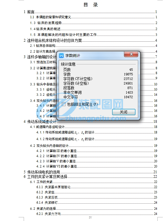
目 录
1 前言 1
1.1 本课题的背景和研究意义 1
1.3 钻床的发展趋势 2
1.4钻床夹具的概述 2
1.5 本课题解决的问题和设计时主要的工作 3
2 连杆组合机床结构设计的总体方案 4
2.1钻床总体结构 4
2.2设计方案选择 4
3 连杆多轴箱的设计 7
3.1 预选加工材料,加工直径 8
3.2 计算高速钢麻花钻轴向切削力及扭矩 8
3.2.1 计算单个钻头轴向切削力 8
3.2.2 计算单个钻头扭矩 9
3.3 钻头中各轴及齿轮的计算 10
3.3.1 齿轮8、9、10、11的计算 10
3.3.2 齿轮5、6、7的计算 14
3.4 双头钻头内各轴的设计 16
3.4.1 计算轴I、VIII的最小直径 16
3.4.2 计算轴II、VII的最小直径 16
3.4.3 计算轴III的最小直径 16
4 传动系统减速设计 18
4.1减速箱内各齿轮设计 18
4.1.1传动系统减速箱齿轮、的设计 18
4.1.2传动系统减速箱齿轮、的设计 19
4.2 双头钻头内各轴的设计 19
4.2.1 计算轴III的最小直径 19
4.2.2 计算轴IV的最小直径 19
4.2.3 计算轴V的最小直径 20
4.2.4 计算轴VI的最小直径 20
5 传动系统电机的选用 21
6 工件的夹紧计算及其选择 22
6.1 工件的夹紧 22
6.1.1 夹紧基本原理理论 22
6.1.2 夹紧座 23
6.1.3 夹紧压板 23
6.1.4 夹紧螺钉 24
6.2 夹紧力的选择 24
6.2.1 夹紧力方向 24
6.2.2 夹紧力的作用点 25
6.2.3 夹紧力的计算 25
6.3 气缸的选型计算 26
6.3.1 气缸的直径确定 27
6.3.2 气缸的选型 28
6.3.3 夹具精度计算与分析 29
7 夹具结构分析与设计 31
7.1 夹具的夹紧装置和定位装置 31
7.2 夹具的导向 32
7.3 钻孔与工件之间的切屑间隙 35
7.4 钻模板 36
7.5定位误差的分析 36
7.6 确定夹具体结构和总体结构 37
结 论 38
致 谢 39
参考文献 40


